|
|
4 years ago | |
|---|---|---|
| .. | ||
| aameeting | 4 years ago | |
| checklist | 4 years ago | |
| groupmeeting | 4 years ago | |
| img | 4 years ago | |
| log | 4 years ago | |
| part | 4 years ago | |
| .nojekyll | 4 years ago | |
| CNAME | 4 years ago | |
| README.md | 4 years ago | |
| index.html | 4 years ago | |
README.md
Frequency Downconverter
In this project, Frequency Downconverter (FDC) is designed to convert signal from Ultra High Frequency (610MHz) to VHF (80MHz). With LT5512 mixer as center IC, surrounding circuit was designed to adjust the input and output impedance to 50Ω, eliminate DC interference as well as block high frequency noise at IF part. PCB was designed and manufactured with the help of Altium Designer and eagleCAD. This product can effectively decrease the cost and complexity of Radio Frequency signal processing.
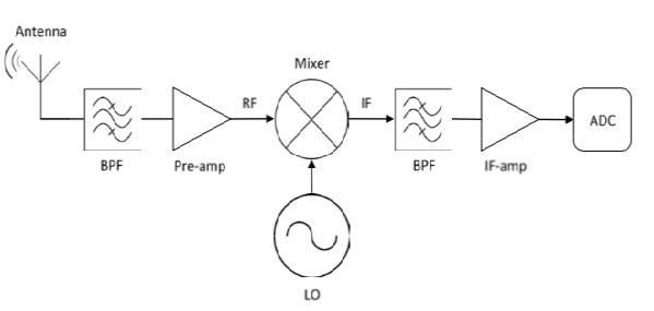
A typical FDC accept two input signal and output the combined signal at f1+f2 and f1-f2. This means that, besides the RF signal input, another low frequency vibration signal, which we called as LO signal, is also needed. Before the RF signal go into the mixer, it needed to be processed through band pass filters as well as amplifiers to make sure that only the signal we expected can go into the mixer. For the output IF signal, band pass filters and amplifiers are also necessary to block the spare f1+f2 signal and keep the signal Hi-Fi. These measures are important to design a high quality FDC.
Objectives
- Learn to solve Engineering problems (i.e. How good is good enough?)
- Learn skills to design and manufacture electrical products
- Obtain skills and experience to cooperate with team
- Make a simple FDC which can work